400GBASE-SR4.2
400GBASE-SR4.2, also called 400GBASE-BD4.2, is a 4-pair, 2-wavelength multimode solution that supports reaches of 70m (OM3), 100m (OM4), and 150m (OM5). It is not only the first instance of an IEEE 802.3 solution that employs both multiple pairs of fibers and multiple wavelengths, but also the first Ethernet standard to use two short wavelengths to double multimode fiber capacity from 50 Gb/s to 100 Gb/s per fiber.
400GBASE-SR4.2 operates over the same type of cabling used to support 40GBASE-SR4, 100GBASE-SR4 and 200GBASE-SR4. It uses bidirectional transmission on each fiber, with each wavelength traveling in opposite directions. As such, each active position at the transceiver is both a transmitter and a receiver, which means 400GBASE-SR4.2 has eight optical transmitters and eight optical receivers in a bidirectional optical configuration.
The optical lane arrangement is shown as follows. The leftmost four positions labeled TR transmit wavelength λ1 (850nm) and receive wavelength λ2 (910nm). Conversely, the rightmost four positions labeled RT receive wavelength λ1 and transmit wavelength λ2.

400G SR4.2 Transceivers:
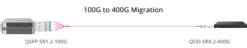
QSFP-DD 400G SR4.2 transceivers facilitate seamless breakout to 4x QSFP28 100G SR1.2 optics, enabling the creation of 400G connections to meet the escalating demands for consumer data rates. Moreover, this breakthrough architecture is achieved while leveraging existing fiber cable infrastructure, thereby optimizing cost-effectiveness.
400GBASE-SR8
400GBASE-SR8 is an 8-pair, 1-wavelength multimode solution that supports reaches of 70m (OM3), 100m (OM4 & OM5). It is the first IEEE fiber interface to use eight pairs of fibers. Unlike 400GBASE-SR4.2, it operates over a single wavelength (850nm) with each pair supporting 50 Gb/s transmission. In addition, it has two variants of optical lane arrangement. One variant uses the 24-fiber MPO, configured as two rows of 12 fibers, and the other interface variant uses a single-row MPO-16.


400G SR8 Transceivers:
400G SR8 transceivers provide the flexibility of fiber shuffling with 50G/100G/200G configurations. These transceivers also support breakout at various speeds for diverse applications, including compute, storage, flash, GPU, and TPU. 400G-SR8 QSFP DD/OSFP transceivers can be employed as 400GBASE-SR8, 2x200GBASE-SR4, 4x100GBASE-SR2, or 8x50GBASE-SR.
400G SR4.2 vs. 400G SR8
As multimode solutions for 400G Ethernet, 400GBASE-SR4.2 and 400GBASE-SR8 share some features, but they also differ in a number of ways as discussed in the previous section.
The following table shows a clear picture of their comparison.
| 400GBASE-SR4.2 | 400GBASE-SR8 | |
|---|---|---|
| Alliance | IEEE 802.3cm | IEEE 802.3cm (breakout: 802.3cd) |
| Max reach | 150m over OM5 | 100m over OM4/OM5 |
| Fibers | 8 fibers | 16 fibers (ribbon patch cord) |
| Wavelength | 2 wavelengths (850nm and 910nm) | 1 wavelength (850nm) |
| BiDi technology | Support | / |
| Signal modulation format | PAM4 signaling | PAM4 signaling |
| Laser | VCSEL | VCSEL |
| Form factor | QSFP-DD, OSFP | QSFP-DD, OSFP |
400GBASE-SR8 is technically simple but requires a ribbon patch cord with 16 fibers. It is usually built with 8 VCSEL lasers and doesn’t include any gearbox, so the overall cost of modules and fibers remains low. By contrast, 400GBASE-SR4.2 is technically more complex so the overall cost of related fibers or modules is higher, but it can support a longer reach.
In addition, 400GBASE-SR8 offers both flexibility and higher density. It supports fiber shuffling with 50G/100G/200G configurations and fanout at different I/O speeds for various applications. A 400G-SR8 QSFP-DD transceiver can be used as 400GBASE-SR8, 2x200GBASE-SR4, 4x100GBASE-SR2, or 8x50GBASE-SR.
400G SR4.2 & 400G SR8: Boosting Higher Speed Ethernet
As multimode fiber continues to evolve to serve growing demands for speed and capacity, both 400GBASE-SR4.2 and 400GBASE-SR8 help boost 400G Ethernet and scale up multimode fiber links too ensure the viability of optical solutions for various demanding applications.
The two IEEE 802.3cm standards provide a smooth evolution path for Ethernet, boosting cloud-based services and applications. Future advances point toward the ability to support even higher data rates as they are upgraded to the next level. The data center industry will take advantage of the latest multimode fiber technology such as OM5 fiber, and use multiple wavelengths to transmit 100 Gb/s and 400 Gb/s over fibers over short reaches of more than150 meters.
FAQs on 400G Transceivers and Cables Definition and Types
Q1: What are 400G transceivers?
A1: 400g optical transceivers are optical modules that are mainly used for photoelectric conversion with a transmission rate of 400Gbps.
They can be classified into two categories according to the applications: client-side transceivers for interconnections between the metro networks and the optical backbone, and line-side transceivers for transmission distances of 80km or even longer.
Concurrently, the electrical port side employs 8 channels of 53Gbps PAM4 electrical signals, packaged in OSFP or QSFP-DD formats. Optical wavelength categorizes 400G optical transceivers into multi-mode (MM) and single-mode (SM), transmission distance classifies them as SR, DR, FR, and LR, and modulation methods distinguish between NRZ and PAM4 (usually favoring PAM4).
Q2: What does it mean when an electrical or optical channel is PAM4 or NRZ in 400G transceivers?
A2: NRZ is a modulation technique that has two voltage levels to represent logic 0 and logic 1. PAM4 uses four voltage levels to represent four combinations of two bits logic-11, 10, 01, and 00. The PAM4 signal can transmit double faster than the traditional NRZ signal.
When a signal is referred to as “25G NRZ”, it means the signal is carrying data at 25 Gbps with NRZ modulation. When a signal is referred to as “50G PAM4”, or “100G PAM4”, it means the signal is carrying data at 50 Gbps, or 100 Gbps, respectively, using PAM4 modulation. The electrical connector interface of 400G transceivers is always 8x 50Gb/s PAM4 (for a total of 400Gb/s).
Q3: What are the 400G transceivers packaging forms?
A3: There are mainly the following six packaging forms of the 400g optical transceiver:
- QSFP-DD: 400G QSFP-DD (Quad Small Form Factor Pluggable-Double Density) is an expansion of QSFP, adding one row to the original 4-channel interface to 8 channels, running at 50Gb/s each, for a total bandwidth of 400Gb/s.
- OSFP: OSFP (Octal Small Formfactor Pluggable, Octal means 8) is a new interface standard and is not compatible with the existing photoelectric interface. The size of 400G OSFP modules is slightly larger than that of 400G QSFP-DD transceivers.
- CFP8: CFP8 is an expansion of CFP4, with 8 channels and a correspondingly larger size.
- COBO: COBO (Consortium for On-Board Optics) means that all optical components are placed on the PCB. COBO has good heat dissipation and small-size. However, since it is not hot-swappable, once a module fails, it will be troublesome to repair.
- CWDM8: CWDM 8 is an extension of CWDM4 with four new center wavelengths (1351/1371/1391/1411 nm). The wavelength range becomes wider and the number of lasers is doubled.
- CDFP: CDFP was born earlier, and there are three editions of the specification. CD stands for 400 (Roman numerals). With 16 channels, the size of CDFP is relatively large.